Manufacturing decision
Choose hole geometry and sheet gauge together, then validate formed stiffness before locking the coating and foam stack.

Manufacturing Application Studies
These representative, anonymized studies show the engineering questions, manufacturing routes, and inspection evidence behind common speaker and amplifier components. Project limits are always confirmed from the controlled customer drawing.
01 · Speaker Grille System
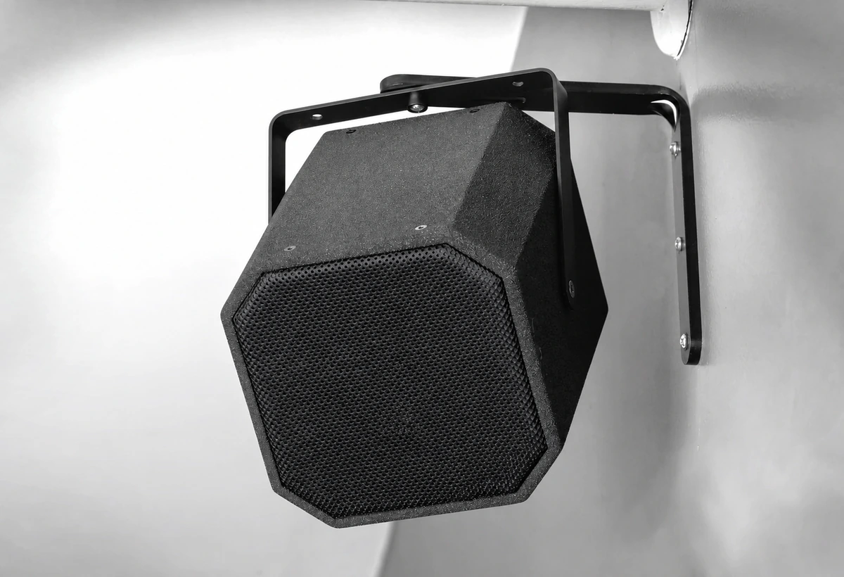
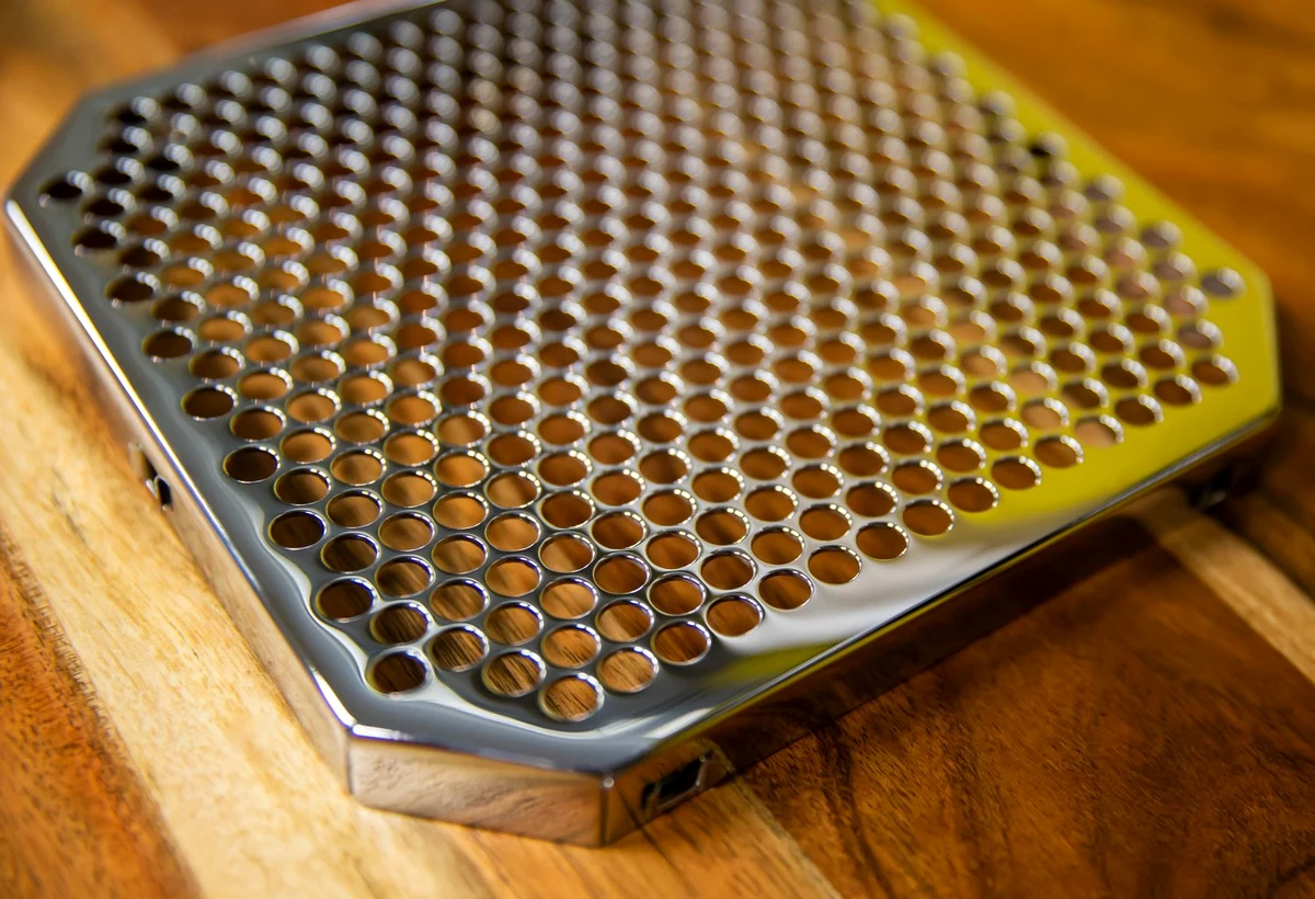
A grille is not simply perforated sheet. Open area influences acoustic transparency; bridge width and formed depth influence stiffness; coating thickness and foam influence final fit.
Choose hole geometry and sheet gauge together, then validate formed stiffness before locking the coating and foam stack.
Hole pattern and pitch, overall profile, edge condition, coating appearance, fit fixture, and approved visual standard.
02 · Line Array Rigging Hardware
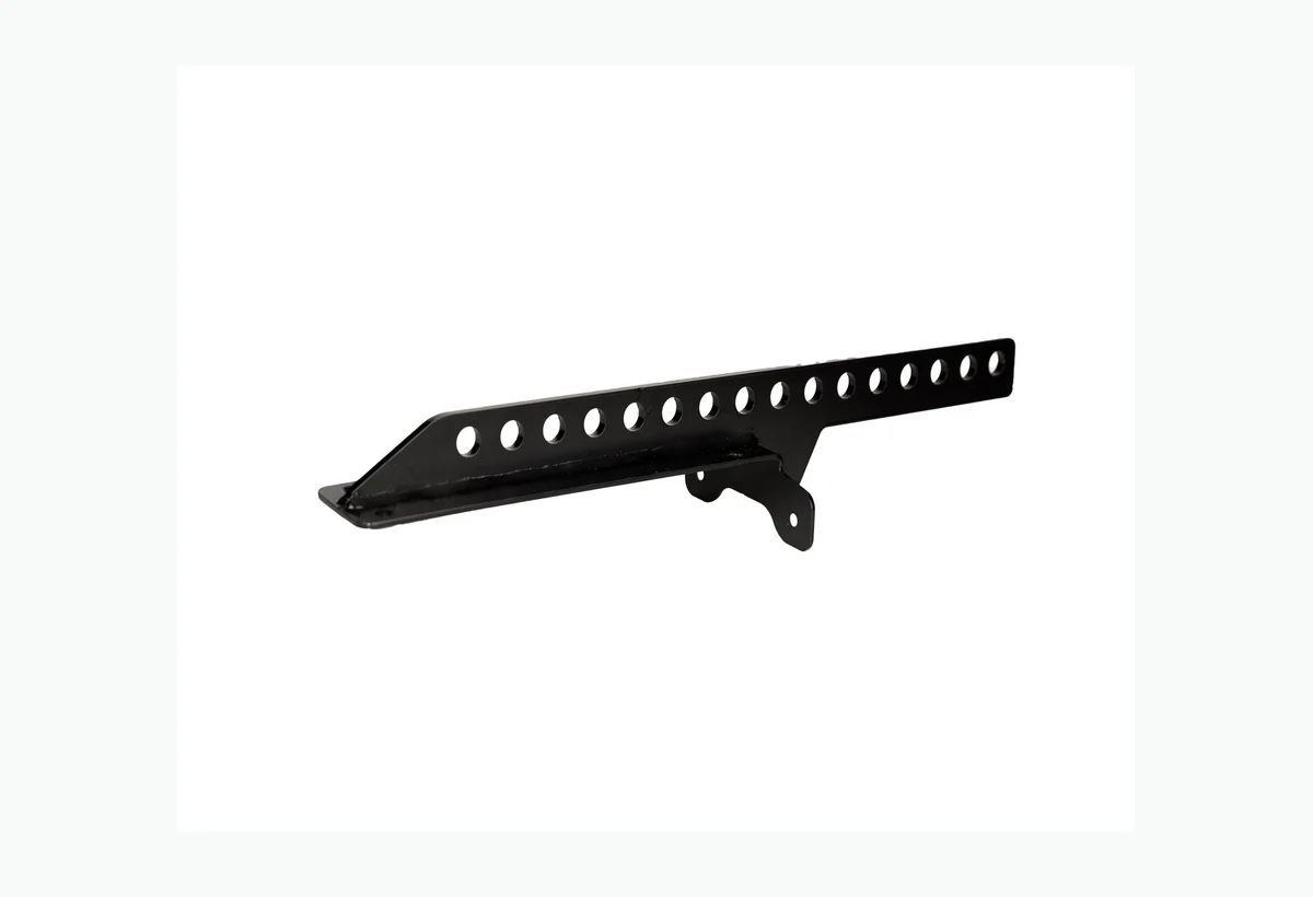
Rigging components need a different review discipline from cosmetic enclosure parts. Material identity, load direction, hole position, edge condition, joining, heat treatment, and finish interfaces must be agreed before production.
Separate safety-critical dimensions and material requirements from general cosmetic features on the drawing and inspection plan.
Material record, first-article dimensions, gauge or fixture result, finish record, and agreed sampling plan. Structural certification remains project-specific.
03 · Amplifier Thermal Housing
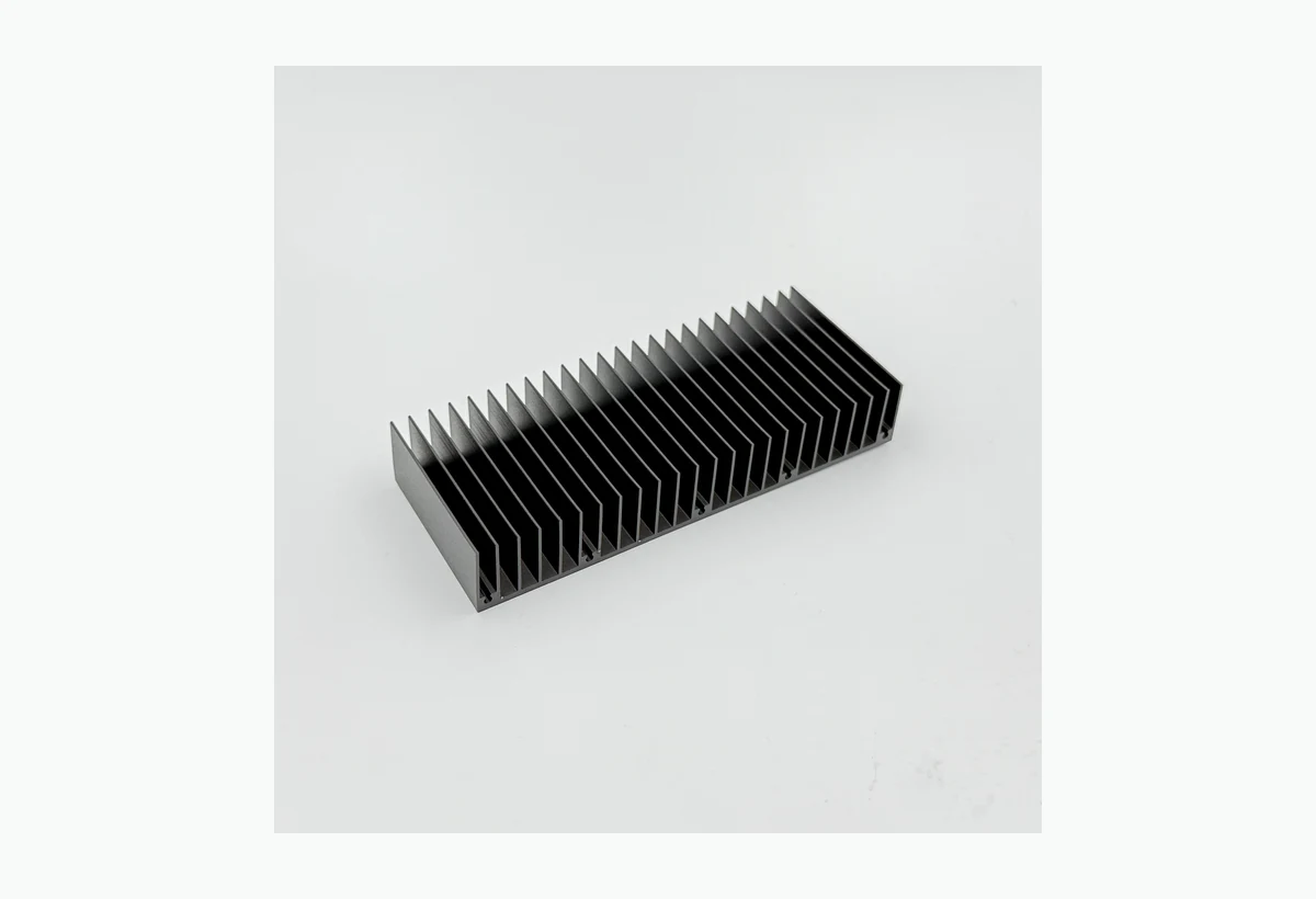
An amplifier housing can combine an extrusion, machined thermal interfaces, cosmetic outer faces, threaded assembly points, connector cutouts, and electrically sensitive finish requirements.
Define functional datums and thermal contact zones before applying cosmetic tolerances to the rest of the housing.
Datum-based dimensions, flatness where specified, thread gauges, finish sample, mask boundary, and trial assembly.
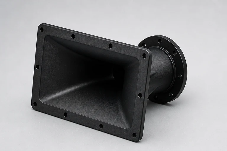
04 · Molded Horn & Functional Plastic
Waveguides, horns, handles, and speaker frames combine visible surfaces with ribs, bosses, clips, draft, shrinkage, and fastening interfaces. The best time to resolve those conflicts is before mold steel is cut.
Protect acoustic and assembly-critical surfaces, while allowing tooling-led adjustments in hidden structural regions.
Approved sample, critical dimensions, texture and color standard, assembly fit, and controlled change record.
Images are representative application and component references. Numerical limits, validation methods, certifications, and acceptance criteria are confirmed for each project from the customer drawing and written quotation. We do not publish customer identities or confidential designs.
See how inspection is planned for each component typeApply the Review
We will identify open manufacturing decisions and propose the next practical step: prototype, DFM revision, tooling review, first article, or production quotation.