
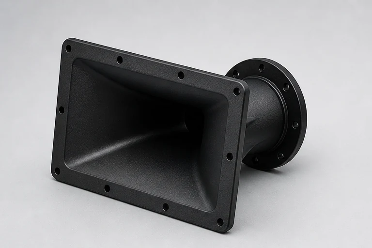
The expensive moment in a molded horn project is not the first quotation; it is cutting tool steel before acoustic, cosmetic, assembly, and molding requirements have been separated. A disciplined DFM review makes those decisions visible while they are still inexpensive to change.
01
Freeze the right surfaces, not the entire model
Acoustic surfaces and driver alignment may be fixed by simulation and prototype testing. Hidden ribs, bosses, draft transitions, fastening features, and local thickness can often change. The DFM package should clearly identify which regions require customer approval for any modification.
Provide the compression driver interface, gasket strategy, cabinet mounting, and nearby parts. A horn that is manufacturable by itself can still fail assembly because screws, tools, wires, or seals do not have enough space.
- Classify acoustic, assembly, cosmetic, and flexible regions
- Share mating parts
- Define revision approval responsibility
02
Select resin from the complete use case
Material choice should consider stiffness, impact, temperature, moisture, UV, flammability, appearance, cost, and availability. Filled materials may increase rigidity but affect flow, surface, wear, and dimensional behavior. Unfilled materials may offer better appearance or toughness but require different structural design.
Avoid specifying only a resin family when the project depends on a particular performance level. Agree whether equivalent grades are allowed and which properties or certifications must be documented.
- State environment and performance priorities
- Define approved grade or equivalency route
- Include color and texture expectations
03
Review parting, gate, ejection, cooling, and texture together
A gate must fill the part without placing unacceptable weld lines or vestige on important surfaces. Ejectors need sufficient area and should avoid acoustic and visible regions. Cooling affects cycle time and dimensional stability, while texture increases draft needs.
Wall thickness should transition smoothly. Ribs and bosses need proportions that provide stiffness without visible sink. Undercuts and side actions may be justified, but each adds tool complexity, maintenance, and timing risk.
- Review marked-up tool concept
- Agree visible defect boundaries
- Avoid hidden tooling complexity without product value
04
Plan sampling as an engineering loop
First shots are information, not automatic production approval. Record molding conditions, measure agreed characteristics, inspect appearance, test assembly, and perform acoustic validation. Corrections should be tracked against a controlled issue list and updated CAD.
The approved sample should be paired with drawing revision, material, color, texture, process assumptions, and acceptance evidence. This becomes the reference for repeat production and helps distinguish real process drift from subjective visual differences.
- T0/T1 issue list and revision control
- Critical dimension and fit report
- Approved appearance and acoustic validation
RFQ
Information to send with the drawing
- Production CAD and marked critical surfaces
- Prototype test status
- Material and compliance targets
- Annual volume and tool-life expectation
- Appearance, validation, and sampling plan
Engineering responsibility
This guide describes manufacturing considerations, not a product certification or universal specification. Acoustic, structural, thermal, electrical, safety, and regulatory validation remain project-specific and must be approved by the responsible product team.