
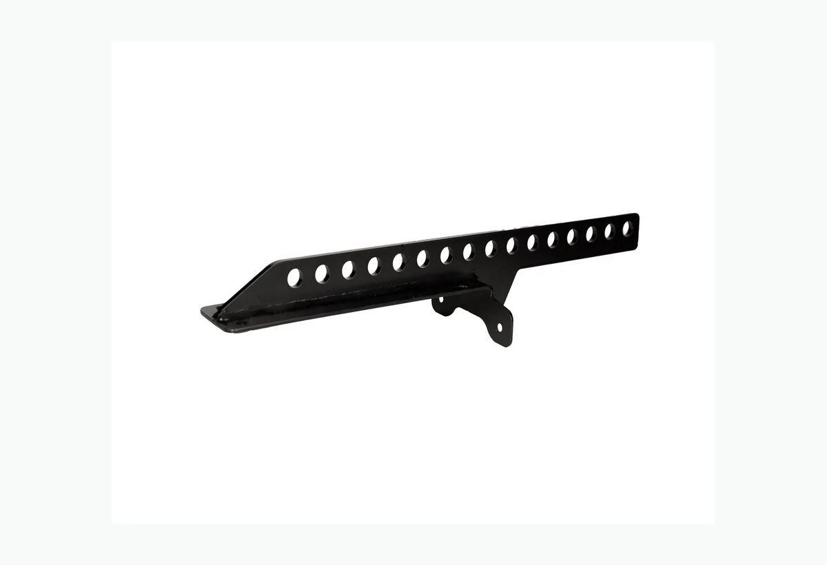
Line array and flown-speaker hardware must be treated as structural product hardware, not ordinary decorative metalwork. The speaker manufacturer owns the system design and validation; the manufacturing plan must preserve the approved material, geometry, interfaces, heat treatment, finish, and traceability.
01
Map the complete load path
Review every interface from cabinet structure through rails, links, pins, brackets, fasteners, and suspension points. A strong individual part does not guarantee a safe assembly if bearing area, edge distance, hole wear, fastener engagement, or load direction is misunderstood.
The controlled drawing should identify safety-critical characteristics and reference the validation basis used by the system designer. Manufacturing feedback can improve access, bend feasibility, inspection, or repeatability, but design changes affecting load must return to the responsible engineer for approval.
- Identify all primary and secondary load paths
- Mark safety-critical characteristics
- Control mating pin and hole interfaces
02
Control material and process history
Material grade, condition, rolling direction where relevant, heat treatment, weld procedure, and surface processing can influence performance. Substitutions should never be made only from a similar strength value without engineering review of toughness, fatigue, corrosion, weldability, and manufacturing history.
Traceability requirements should be agreed at quotation: mill certificate, batch identification, heat-treatment record, plating or coating record, and retention period. Not every part needs the same documentation, but the requirement must be explicit before price and lead time are fixed.
- No unapproved material substitution
- Define certificate and batch needs
- Review welding and heat effects
03
Protect critical geometry through finishing
Hole position, diameter, edge distance, bend location, flatness, and mating profile can affect assembly and load distribution. Burrs, sharp edges, weld distortion, or excessive coating build may interfere with pins and joints even when the raw part was correct.
Masking, post-finish gauges, and assembly fixtures should be considered for interfaces sensitive to plating or powder coating. A finish selected for corrosion must also be compatible with contact wear and galvanic conditions in the complete system.
- Inspect after the final relevant process
- Gauge pin and mating interfaces
- Define edge and burr acceptance
04
Agree validation ownership and evidence
Dimensional inspection and material records do not replace structural validation, proof testing, fatigue assessment, or regulatory review. The manufacturer and customer should state who owns design validation and which production tests, if any, are required.
A practical release package may include first-article dimensions, material identity, process records, visual and coating checks, assembly fit, and customer-approved samples. Any change to material, source, tooling, or critical process should follow written change control.
- State engineering validation owner
- Define production test and sampling
- Require change approval for critical inputs
RFQ
Information to send with the drawing
- Controlled drawing with critical characteristics
- Load case and validation responsibility
- Material condition and certificate requirements
- Finish and corrosion environment
- Inspection, testing, traceability, and change-control needs
Engineering responsibility
This guide describes manufacturing considerations, not a product certification or universal specification. Acoustic, structural, thermal, electrical, safety, and regulatory validation remain project-specific and must be approved by the responsible product team.